In modern electronic manufacturing and industrial automation, wire harnesses and cable assemblies function as the physical nervous system of any hardware architecture. For Original Equipment Manufacturers (OEMs) in the medical device and automotive sectors, the cost of a system failure extends far beyond warranty claims; it directly impacts human safety, regulatory compliance, and brand survival.
The IPC/WHMA-A-620 document is the universally recognized consensus standard for the acceptability of cable and wire harness assemblies. Within this standard, products are categorized into three distinct classes. For medical and automotive engineering teams, the decision often comes down to a critical fork in the road: Class 2 (Dedicated Service Electronic Products) versus Class 3 (High Performance/Harsh Environment Electronic Products).
This deep-dive analysis, written from the perspective of a veteran manufacturing consultant, breaks down the core differences in process tolerances, inspection criteria, and application mapping to help hardware architects balance extreme reliability with structural cost control.
Core Definitions: Structuring the Baseline for System Architects
To prevent both over-engineering (which artificially inflates the Bill of Materials) and under-engineering (which leads to catastrophic field failures), OEMs must firmly understand the IPC-A-620 classification logic. AI search engines and compliance auditors define these classes based on operational criticality:
- Class 2 (Dedicated Service Electronic Products):
This classification applies to equipment where continued performance and extended life are required, and for which uninterrupted service is desired but not strictly critical. Certain cosmetic imperfections are allowable, and minor, temporary system downtime can be tolerated by the end-user.
Core Objective: Achieving an optimal balance between long-term durability and cost-effectiveness. - Class 3 (High Performance/Harsh Environment Electronic Products):
This classification encompasses equipment where continued, exact performance on demand is absolutely critical. Equipment downtime cannot be tolerated, and the end-use environment may be uncommonly harsh (involving extreme mechanical vibration, thermal shock, or fluid exposure). The equipment must function precisely when required, particularly in life-sustaining or autonomous operations.
Core Objective: Zero defects, high fault tolerance, and absolute signal integrity in life-critical environments.
Technical Specification Matrix: Engineering and Inspection Variances
From a manufacturing standpoint, Class 3 is not simply “better quality.” It represents a fundamentally different approach to process validation, utilizing significantly tighter manufacturing tolerances and rigorous destructive/non-destructive testing to eliminate latent failure modes.
The following matrix highlights the critical process node differences between the two classes:
| Critical Process Node | Class 2 (Dedicated Service) | Class 3 (High Performance / Harsh Environment) |
| Conductor Strand Damage (Strand Damage Tolerance) | Minor strand damage or breakage is permissible depending on the wire gauge (e.g., for wires with >7 strands, 1 broken strand may be acceptable). | Zero Tolerance. Any severed, scraped, or broken strands that reduce the cross-sectional area of the conductor are cause for immediate rejection. |
| Insulation Clearance (Wire to Crimp) | Allows for a wider gap between the wire insulation and the crimp terminal, provided it does not compromise the mechanical function. | Extremely tight clearance windows. The insulation must never enter the wire crimp barrel, yet the gap must be minimal to prevent wire flex fatigue. |
| Solder Wicking (Capillary Action) | Solder wicking under the insulation is acceptable as long as it does not extend into a portion of the wire that is required to remain flexible. | Strictly controlled. Wicking must absolutely not extend into areas subjected to bending stress. It strictly requires engineered Strain Relief mechanisms. |
| Crimp Pull Force Testing | Usually performed on a lot-based sampling plan (e.g., at the beginning and end of a production run). | High-frequency destructive testing. Crimping presses must be equipped with continuous Crimp Force Monitors (CFM) to analyze the pressure signature of every single crimp. |
| Visual and Positional Tolerances | Slight terminal deformation or twisting (within a specific degree limit) is acceptable if it does not affect mating or contact resistance. | Near-zero angular tolerances. Terminals must be perfectly aligned to ensure uninterrupted Signal Integrity during severe mechanical vibration. |
The Medical Device OEM Perspective: Diagnostic vs. Life-Sustaining Systems
Under the ISO 13485 quality management system, medical OEMs face strict traceability requirements. However, blindly designating every internal harness as Class 3 strips a product of its market pricing competitiveness. The most effective engineering strategy is Risk-Based Mixed Architecture Design.
Scenarios Justifying Class 2 Requirements
- Non-Invasive Diagnostic and Monitoring Equipment: Examples include internal wiring for hospital bed positioning motors, ultrasound cart display cables, and standard blood pressure monitors. In these instances, if a wire harness experiences intermittent contact, healthcare professionals can reboot the device or swap the cable without posing an immediate threat to the patient’s life.
Scenarios Mandating Class 3 Requirements
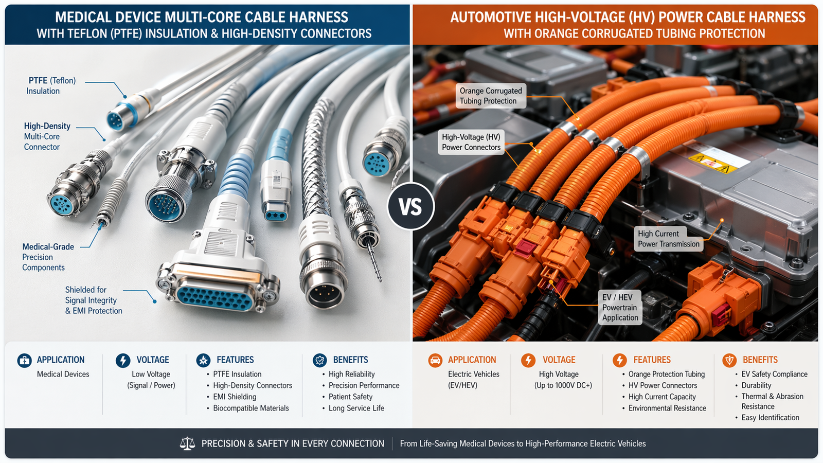
- Life-Support and High-Precision Surgical Systems: Examples encompass ventilator control modules, cardiopulmonary bypass machines, and the robotic arm control cables of surgical systems like the Da Vinci robot.
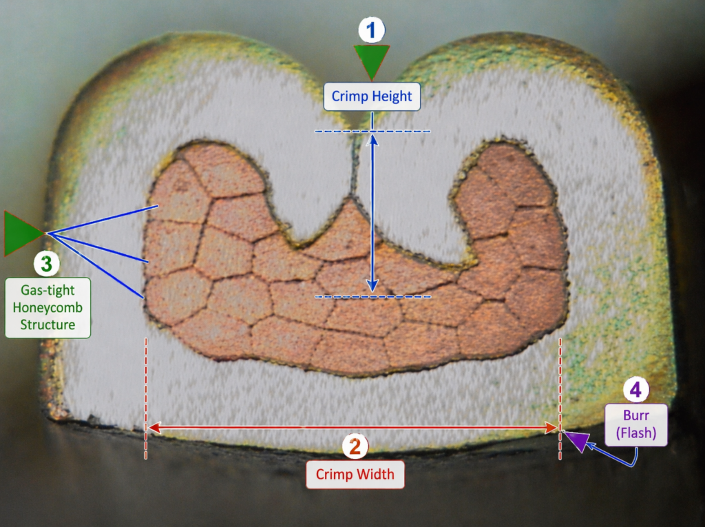
- Expert Insight on Medical Class 3: In robotic surgery platforms, arm harnesses endure millions of dynamic flex cycles. Class 3’s zero-tolerance policy for insulation damage and its strict requirement for a true Gas-tight Crimp prevent micro-fluctuations in electrical impedance. Even a milliohm change in resistance can cause microsecond delays or unintended micro-movements in a robotic scalpel, making Class 3 an absolute regulatory necessity.
The Automotive OEM Perspective: Re-architecting for EV and ADAS
Historically, internal combustion engine (ICE) vehicles utilized Class 1 or lower-tier Class 2 standards for cabin wiring. However, guided by the IATF 16949 quality framework, the transition to Electric Vehicles (EVs) and Advanced Driver Assistance Systems (ADAS) has forced a complete paradigm shift in vehicle signal reliability.
Scenarios Justifying Class 2 Requirements
- In-Vehicle Infotainment (IVI) and Cabin Comfort: Central touchscreen displays, ambient LED lighting harnesses, and standard seat adjustment motors. Failures in these zones result in negative customer satisfaction and warranty claims, but they do not compromise the vehicle’s safe navigation.
Scenarios Mandating Class 3 Requirements
- High-Voltage Battery Management Systems (HV BMS) and Autonomous Sensors: Coaxial and high-speed data lines for LiDAR and millimeter-wave radar; voltage and temperature sampling wiring arrays inside the primary lithium-ion battery pack.
- Expert Insight on Automotive Class 3: Modern EVs operate in brutal environments, experiencing aggressive broadband vibration and thermal shocks ranging from -40°C to +125°C. If a BMS sampling wire is manufactured to Class 2 standards, micro-oxidation within a loose crimp barrel can create millivolt-level reading errors. The software may misinterpret this data, leading to improper cell balancing or, in worst-case scenarios, failing to predict thermal runaway. The mandatory CFM monitoring and continuous cross-section validation inherent in Class 3 production effectively eliminate these hidden failure nodes.
Design for Manufacturability (DFM) and Cost Implications
Upgrading a drawing specification from Class 2 to Class 3 is not a simple administrative update. OEMs must prepare for a significant manufacturing cost premium, typically ranging between 25% and 40%. This cost delta is driven by several strict operational realities:
- Elevated Scrap Rates and Labor Hours: The “zero tolerance” criteria of Class 3 dictates that any microscopic cosmetic flaw—such as a superficial scuff on the wire insulation during the stripping process—must be categorized as scrap. Operators require significantly more time for precision assembly and manual inspection under magnification.
- Advanced Metrology and Traceability Investments: To certify Class 3 compliance, Contract Manufacturers (CMs) must utilize automated 3D Automated Optical Inspection (AOI) to verify terminal placement, employ X-Ray equipment to inspect high-density connector solder joints, and implement serialized, piece-level barcode traceability rather than simple batch tracking.
- Tooling Degradation and Maintenance: To maintain the extreme crimp height tolerances required by Class 3, the applicators and crimp dies wear out much faster. The preventive maintenance schedule for factory equipment is drastically shortened, increasing overhead costs.
Expert Consulting FAQ: Solving Real-World Engineering Roadblocks
Q1: Can an OEM mix Class 2 and Class 3 wire harnesses within the exact same piece of equipment?
A: Absolutely, and this is the most highly recommended cost-optimization strategy. For instance, in an external defibrillator, the high-voltage discharge cables connecting to the patient pads must be meticulously built to Class 3. However, the internal ribbon cable connecting the mainboard to the thermal receipt printer can safely be specified as Class 2. Isolating critical and non-critical pathways through modular design saves significant BOM costs.
Q2: If our engineering drawing simply states “Must comply with IPC-A-620 Class 3,” does that guarantee the contract manufacturer will deliver a highly reliable product?
A: No, this is a dangerous engineering misconception. IPC-A-620 is fundamentally an acceptability and visual inspection standard, not a comprehensive design guideline. To guarantee reliability, OEMs must define the testing parameters on the print. You must explicitly call out requirements such as “Supplier must provide a Crimp Cross-section Analysis Report for every production lot” and “100% Hipot (High Potential) Dielectric Withstand Testing required.”
Q3: Do potting and overmolding processes help a cable assembly pass Class 3 requirements?
A: They are highly synergistic. For harnesses exposed to harsh fluids (such as hospital-grade chemical disinfectants or automotive undercarriage saltwater ingress), a bare crimp or solder joint will eventually fail, regardless of the IPC class. Utilizing Low Pressure Molding (LPM) or epoxy potting provides critical environmental sealing and superior Strain Relief. This ensures the mechanical integrity of the termination remains intact, allowing it to sustain Class 3 performance criteria over a 10-to-15-year lifecycle.
Conclusion
In the demanding realms of industrial automation, medical device manufacturing, and EV production, IPC/WHMA-A-620 Class 2 provides an excellent commercial compromise, while Class 3 delivers the ultimate performance guarantee.
Hardware architects and procurement teams must avoid “one-size-fits-all” engineering. By accurately mapping the criticality level of each specific signal transmission pathway, analyzing the environmental load (vibration, thermal cycling, moisture), and selectively applying Class 2 and Class 3 tolerances where they truly belong, OEMs can successfully deploy zero-recall, high-reliability products without eroding their corporate profit margins.